
Product details
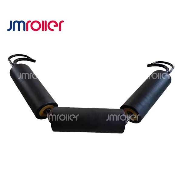
Garland roller comprises either 3-roller or 5-roller joined together at the
ends of their
respective shafts by special lugs, to form a continuous ’chain’ of roller. On
either end of this ‘chain’, the shafts are connected to an attachment bracket
which enables the roller set to be attached to the conveyor stringer
structures.
Garlands can be made:
1. For all types of rollers – Steel, HDPE SUPREME and Rubber impact or rubber
disc.
2. In 2, 3 or 5 roll configuration.
3. With a variety of end connectors – chain, handle, bobbin or quick
release.
Application:
Mining
Steel mill
Cement plant
Power plant
Chemical Plant
Sea Port
Storage
etc.
Application and selection guide
Garland rollers link individual rollers into a suspended assembly that follows a conveyor’s belt profile. The connection style and supporting arrangement matter as much as the roller shell, especially when a replacement must fit an existing suspension system.
Where this product fits
Use the garland arrangement where the conveyor design calls for a flexible suspended roller chain. Explain whether the assembly carries material, supports the return strand or operates beneath a loading zone.
Information for a suitable proposal
Show the number and position of rollers, connector details and attachment points. Identify the existing end brackets and available clearances rather than ordering individual rollers without checking the assembly geometry.
The roller, its mounting frame and the belt form one working assembly. Confirm the shell length, shaft end form and installed clearances against the existing structure. Photographs help identify the arrangement, while an approved drawing is preferable when the replacement must fit an established conveyor.
Installation and maintenance considerations
Inspect connectors, suspension points and shaft ends together. Replacing a worn roller while retaining a damaged connecting part can leave the assembly incorrectly supported.
Include belt speed, conveyed material, expected contamination and the position on the conveyor in the inquiry. A carrying position, a loading point and a return strand expose a roller to different duties. Ask for the proposed bearing and sealing arrangement to be checked against those conditions rather than choosing by outside appearance alone.
For related options, explore roller sets and supporting arrangements or discuss the application with JuMing.