
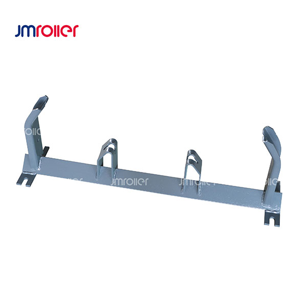
 Conveyor Frame
Carrying frame
A carrying frame holds the roller arrangement beneath the loaded conveyor belt. Its mounting interface and roller positions…
View detailsConveyor Frame: applications and selection Conveyor frames hold rollers in the geometry required to support the belt and connect the station to the main conveyor steelwork. The range includes carrying frames, brackets, off-set arrangements…
Explore the available designs, then review the application and selection guide below. Send a drawing or operating requirements to discuss the appropriate specification.
Conveyor Frame
A carrying frame holds the roller arrangement beneath the loaded conveyor belt. Its mounting interface and roller positions…
View details Conveyor Frame
Roller brackets provide the local mounting interface between a roller shaft and its supporting structure. Their form and…
View details Conveyor Frame
An off-set frame locates rollers in a staggered arrangement along the conveyor direction. The relative positions of its…
View details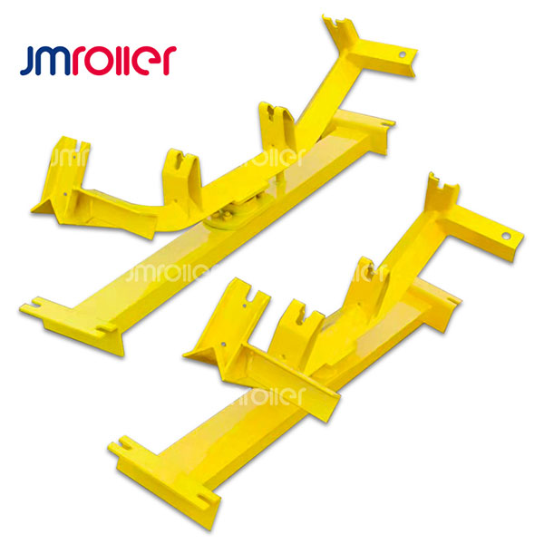 Conveyor Frame
A self aligning carrier frame supports the carrying roller arrangement while allowing the designed aligning movement. Its pivot,…
View details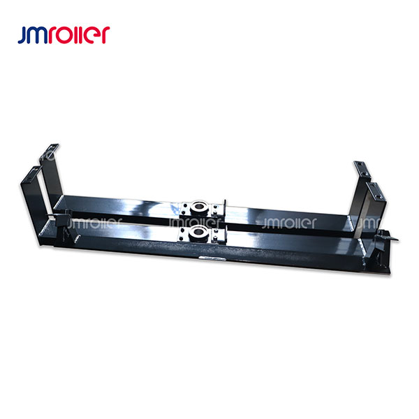 Conveyor Frame
A self aligning return frame provides the mounting structure for a return-side aligning roller assembly. Its geometry must…
View detailsConveyor frames hold rollers in the geometry required to support the belt and connect the station to the main conveyor steelwork. The range includes carrying frames, brackets, off-set arrangements and self aligning carrier or return frames. A frame enquiry should show the assembled roller position and mounting interface rather than only the overall width.
A carrying frame maintains the intended belt trough, while an off-set frame places supports at defined positions along the travel direction. Self aligning frames add a pivot or other movement that requires clearance and compatible surrounding structures. Brackets provide the local connection at a roller shaft. These arrangements are not interchangeable solely because they accept rollers of a similar size. Confirm where the station belongs and whether rollers are included in the requested assembly.
Before fitting a replacement, check the main support structure for distortion and establish alignment with adjacent stations. Roller shafts should seat correctly without being forced into mismatched brackets. For moving assemblies, inspect pivots and stops and keep the intended movement path clear. A drawing of the installed station helps identify a practical replacement and can prevent repeated wear caused by a damaged or unsuitable mounting location.
Explore related products: Carrying frame; Bracket; Off-set Frame; Self Aligning Carrier Frame; Self Aligning Return Frame.